Spectroscopic reflectometry
Technology Spectroscopic reflectometry
Spectroscopic reflectometry (SR) is an optical technique which can measure the thickness by analyzing an interference spectrum created by total
summation of a number of beams reflected from the sample once or many times when the broadband light is incident on the sample. Due to a short
coherence length of the broadband light, SR is used for the thickness measurement of thin film with sub-μm thickness. In the optical configuration,
SR is very similar with spectral resolved interferometry (SRI). But, SR is totally different with SRI in terms of using self-interference inside the thin film
without reference mirror. In other words, the interference spectrum in SR represents the reflectance spectrum.
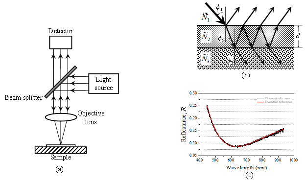
Fig. 1. (a) Optical configuration of simple reflectometer, (b) reflections and transmissions for two interfaces in single-layer thin film structure, and (c)
examples of measured and calculated reflectances.
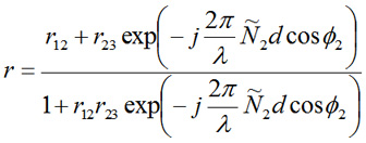
Fig. 1(a) shows a basic optical configuration of SR. A broadband light source like tungsten halogen lamp or LED is used as a light source, and a spectrometer is used as a detector. But, unlike SRI, it’s unnecessary to use a reference mirror. The propagation path of light incident on the thin film sample can be illustrated using multiple reflections and transmissions, as depicted in Fig. 1(b). The total reflectance, R can be obtained from a spectrometer in the form of an interference spectrum, which is called as ‘reflectance spectrum’. A sample structure shown in Fig. 1(b) consists of a single layer thin film and a substrate. For easy understanding, the materials of 1st, 2nd, and 3rd layers from the top are modeled as air, a thin film, and a substrate, respectively. In Fig. 1(b), Ñi and ϕi (i=1, 2, 3) represent the complex refractive index and incident angle in ith layer, respectively. In Eq. (1), a total reflection coefficient, r can be expressed as a function of light wavelength (λ), complex refractive index (Ñ2), incident angle (ϕ2) at the thin film-substrate interface, and thin film thickness (d). The total reflectance, R can be calculated as r·r*, where r12 and r23 represent the Fresnel reflection coefficients at air-thin film interface and thin film-substrate interface, respectively.
Fig. 1(a) shows a basic optical configuration of SR. A broadband light source like tungsten halogen lamp or LED is used as a light source, and a spectrometer is used as a detector. But, unlike SRI, it’s unnecessary to use a reference mirror. The propagation path of light incident on the thin film sample can be illustrated using multiple reflections and transmissions, as depicted in Fig. 1(b). The total reflectance, R can be obtained from a spectrometer in the form of an interference spectrum, which is called as ‘reflectance spectrum’. A sample structure shown in Fig. 1(b) consists of a single layer thin film and a substrate. For easy understanding, the materials of 1st, 2nd, and 3rd layers from the top are modeled as air, a thin film, and a substrate, respectively. In Fig. 1(b), Ñi and ϕi (i=1, 2, 3) represent the complex refractive index and incident angle in ith layer, respectively. In Eq. (1), a total reflection coefficient, r can be expressed as a function of light wavelength (λ), complex refractive index (Ñ2), incident angle (ϕ2) at the thin film-substrate interface, and thin film thickness (d). The total reflectance, R can be calculated as r·r*, where r12 and r23 represent the Fresnel reflection coefficients at air-thin film interface and thin film-substrate interface, respectively.
To measure the thin film thickness (d), the complex refractive indices and incident angles should be known in advance. The total reflectance at each
wavelength according to d can be calculated using such information. As a result, the thin film thickness, d can be determined as a specific value which
makes the modeled total reflectance spectrum that most closely resembles the measured total reflectance spectrum. In thin film thickness measurement
process, a least square method which determines the minimum value of the sum of squared differences between theoretical and measured reflectance
spectrum at every wavelength is used among various optimization techniques is generally used. For example, Fig. 1(c) represents a measured reflectance
spectrum (black) and a modeled reflectance spectrum (red) determined using the least square method.

1107, 114, Gyeryong-ro, Yuseong-gu, Daejeon, Republic of Korea
TEL : +82-70-7122-2000 FAX : +82-70-7159-1353 E-MAIL : info@meter-lab.com
TEL : +82-70-7122-2000 FAX : +82-70-7159-1353 E-MAIL : info@meter-lab.com
Copyright © 2025 Meter-Lab. Inc. All rights reserved. designed by website.co.krblog